Enhancing Lubrication System Reliability—Initiatives at Tata Steel
In the steel industry, lubricants play an important role in keeping the equipment running and in a healthy condition. The lubrication requirement of the steel industry is very challenging, as the operating conditions of the machinery are very harsh with respect to load, temperature, dust, and water ingress.
Lubrication costs typically consume between 3% and 5% of the total maintenance budget. While lube costs appear low as a percentage of the overall budget, their impact on every other maintenance item is significant if lubes are not effectively employed. The "Six R's" of lubrication – the right lubricant, in the right amount, at the right time, at the right place, with the right method and the right people to lubricate- are essential to the successful performance of any equipment.
Right Product & Quality: If the lubricant is not correct & fit for purpose, it may result in failure. The following needs to be checked:
• Does the product meet our specifications?
• Is this the right product for the application?
• Does it meet OEM requirements?
• Does it meet the requirements of the equipment?
• Have the operating conditions of the equipment changed from original design specifications? (Speed,
load, temperature)
• Is there a better alternative?
The "Right Quality" of the lubricant needs to be verified through:
• Lubricant Condition Monitoring
• Contamination Control
• Proper Sealing
Right Place: If the lubricant is not in the equipment, it cannot do its job. In the event of a lubrication failure, the first step is to check whether the lubricant actually reached the part or if the lack of lubricant caused the issue. Supply lines may have been damaged, broken, or blocked. There might also have been signs that the lubricant was not reaching the part, such as abnormal temperature, vibration alarms, or noisy operation. It is also important to note how the user responded when these alarms or warning signs appeared.
Right Time: All equipment has a defined lubrication frequency. This could be a scheduled oil change, the time between regreasing intervals, or the set delivery schedule of drip or pressure systems. If the lubricant does not reach the equipment before the existing lubricant wears out or runs out, the equipment is at risk of failure. The critical point is whether the lubricant arrived in time to prevent damage.
Right Amount: Every piece of equipment requires a specific volume of lubricant to protect its moving parts. This volume is usually specified by the OEM or guided by established user practices. The essential check is whether the correct amount of lubricant was provided and if it was sufficient for the application. Confirmation can come through flow meters, positive displacement valves, measuring containers, or other reliable methods that verify the right quantity has been delivered.
Right Method: There are several ways to get lube into equipment.
• Manual application (grease gun/oil can / pump)
• Centralized lubrication systems (high-pressure, timer-operated grease pumps & measuring valves;
recirculation oil systems; level-operated oil top-up systems; open gear spray systems; etc.)
• Semi-automated systems (single-point lubricators; drip feeders, etc.)
Is the system fit for purpose? Is it working correctly & in good condition? Does it meet OEM requirements?
Right People
The competence of the individuals carrying out lubrication plays a decisive role in equipment reliability. In some plants, multi-skilled workers operate and maintain equipment, but not all may have the focus or knowledge needed for lubrication tasks. Having dedicated lube personnel can make a significant difference. The people performing lubrication must understand product choice, the six "R's" of lubrication, and the importance of consistency. A structured system should also be in place to ensure that lubrication is scheduled and completed correctly, aligning with the six "R's" every time.
The present paper discusses case studies from Tata Steel that illustrate these principles in action.
Case Study 1: Mill Chock Bearing Failure Reduction at NBM
The New Bar Mill was established in the year 2005 to produce long products, i.e., TMT (Thermo Mechanically Treated) bars. It rolls billets having a cross-section of 150×150 mm² and a length of 12 m into TMT bars having a wide range of diameters, i.e., 8 mm, 10 mm, and 12 mm, by the process of Hot Rolling in the fig below.
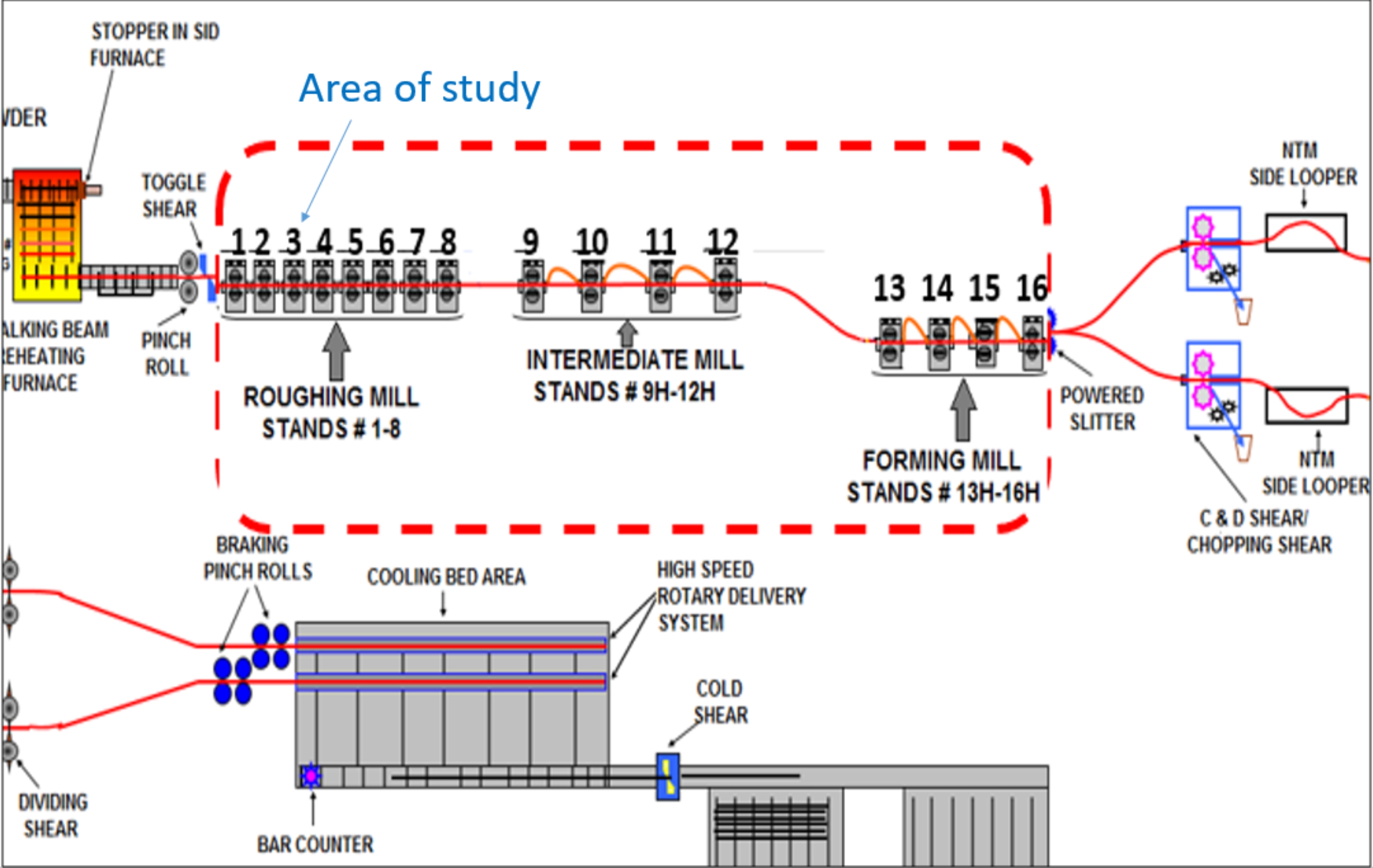
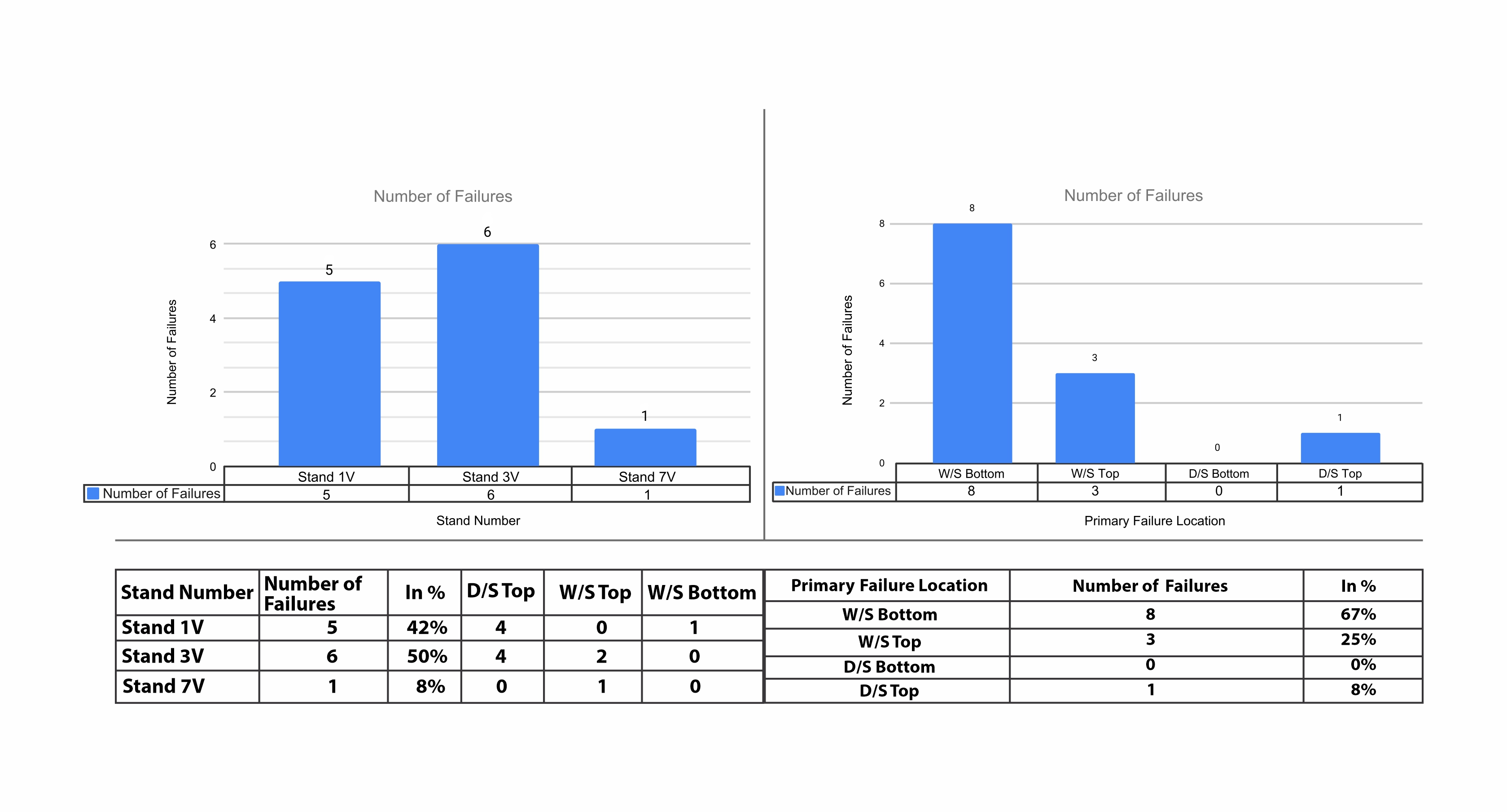
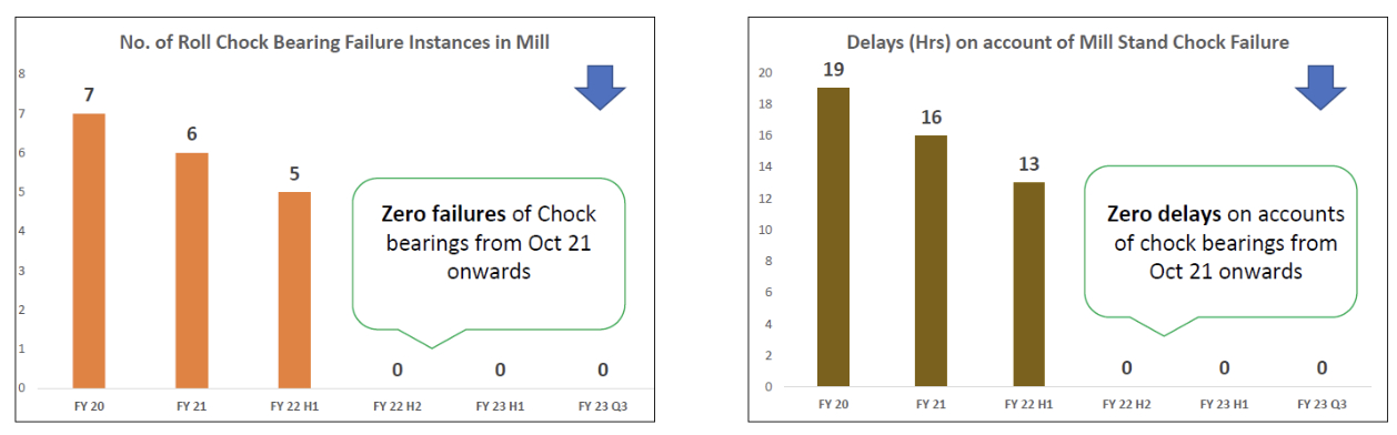
There were total of 12 chock bearing failures observed at NBM since 2015 till March 2021. Failures were mainly at Vertical stands no. 1, 3 & 7.
Based on Root Cause Failure Analysis (RCFA) of failed bearings, following action points were decided:
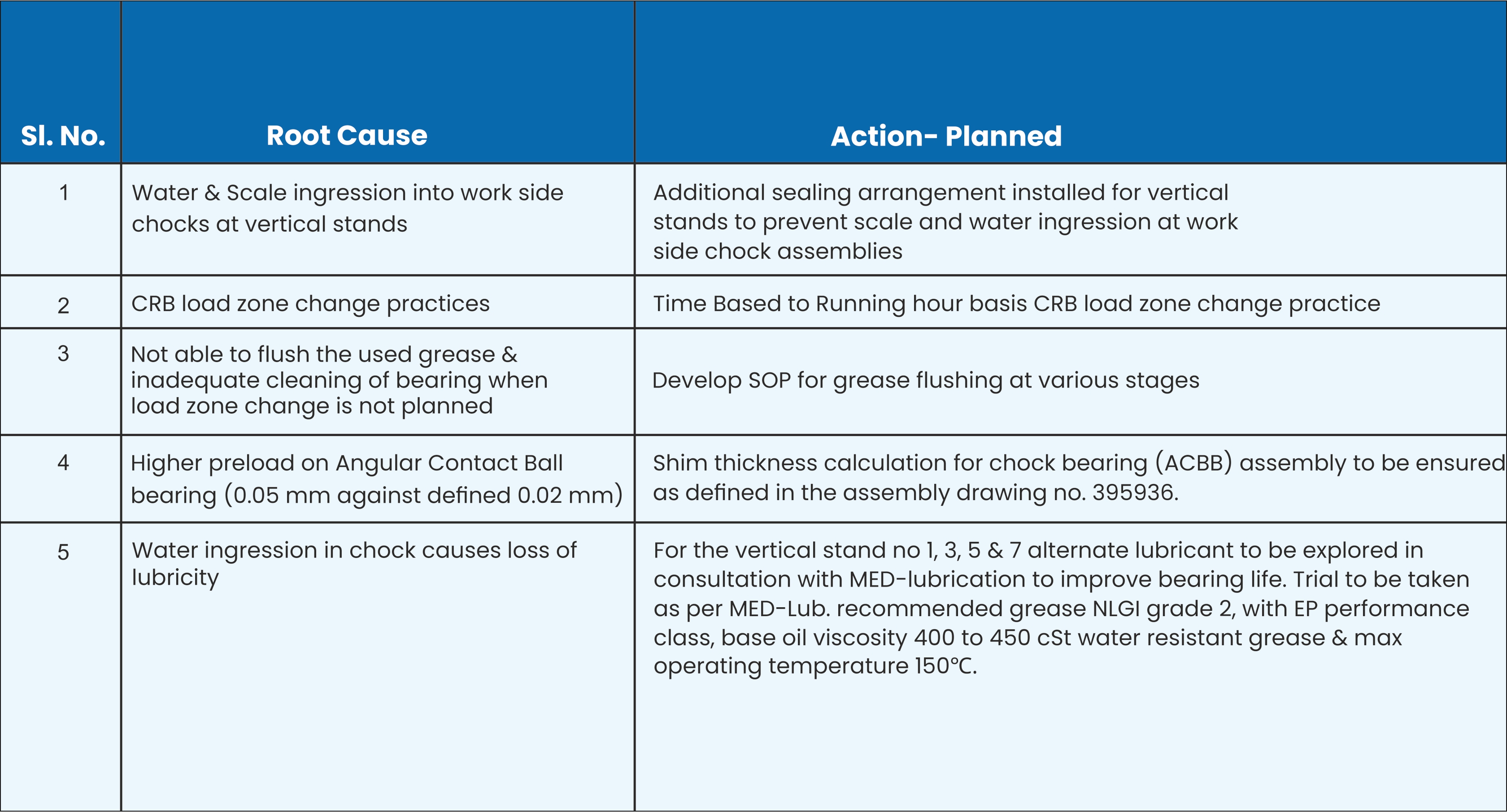
With all the actions completed, we have been able to achieve zero failures of chock bearings from October 2021 onwards.
Case Study 2: Frequent failure of middle bearing (SRTB) of Roksh Separator (90 S2) rotor at Pellet Plant
The 6 MTPA pellet plant has 2 nos. of Roksh Separators for classifying the oversize and product fines from the Ball Mill. The product fines (after grinding from Ball Mill) pass through the Roksh Separator to bag houses.
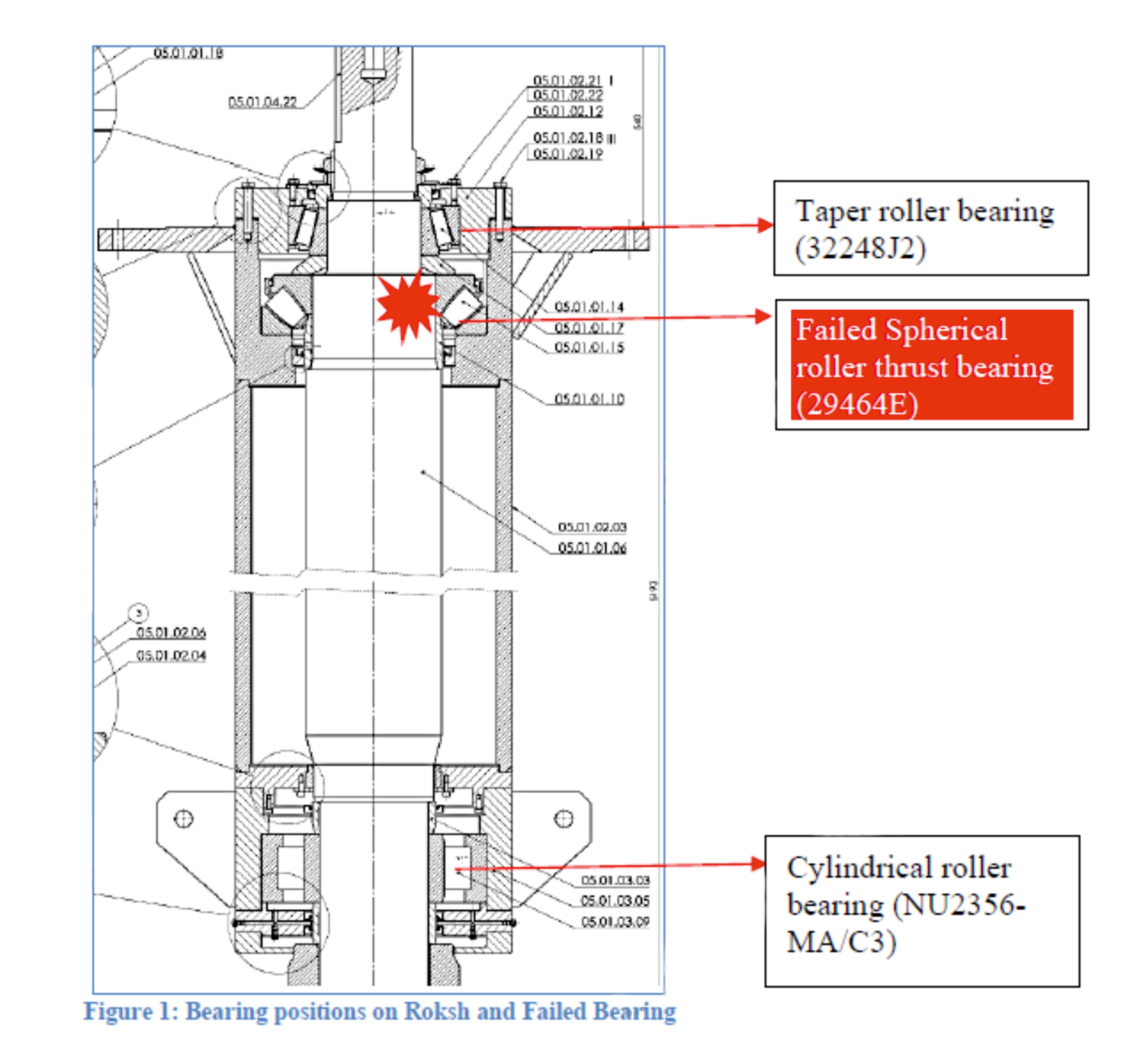
The Roksh Rotor shaft has a three-bearing arrangement: a tapered roller bearing at the top, a spherical roller thrust bearing (SRTB-29464 E – SKF and dimension (320 x 580 x 155)) in the middle, and a cylindrical roller bearing at the bottom. The housing ID for the Spherical Roller Thrust (SRT) Bearing is 585 mm, and the cage diameter at the rotor bottom is 5858 mm. The bearing arrangement is shown below.
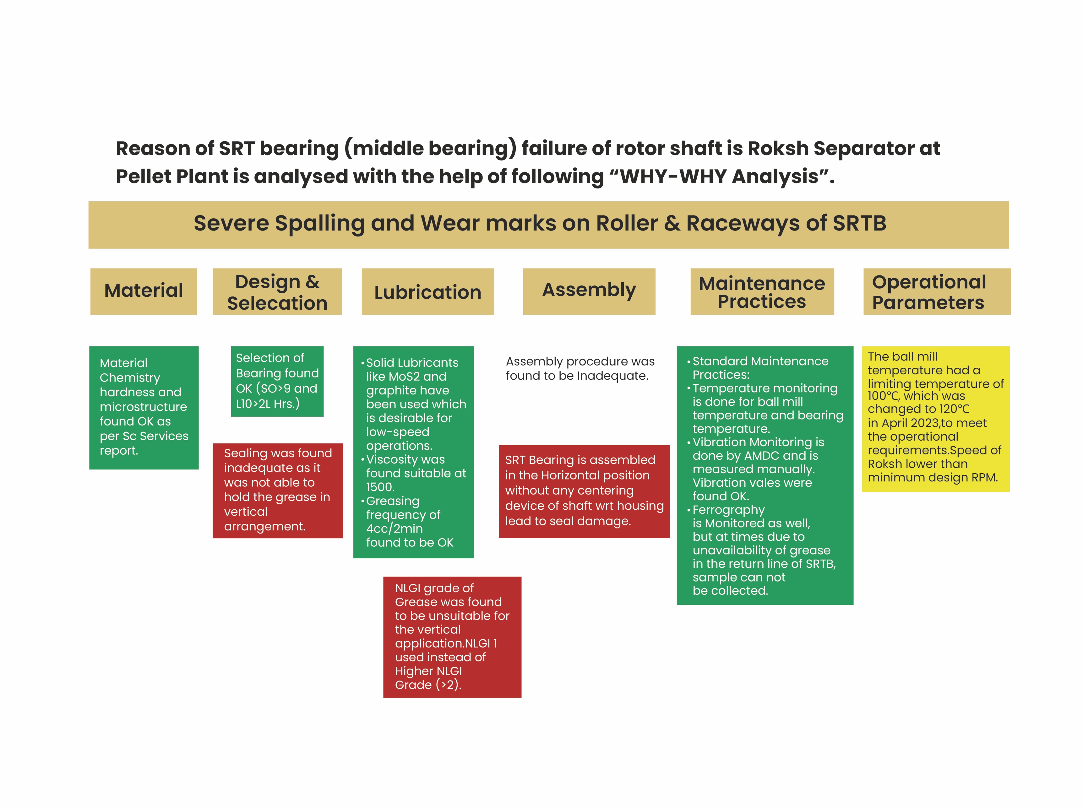
The Roksh separator spherical roller thrust bearing failed because of the following reasons:
• Inadequate sealing arrangement at the bottom of the SRT bearing causing less quantity of grease in the
middle bearing led to severe wear in raceway and rolling elements. The grease was leaking out from the
bottom seal and did not follow the grease return path.
• Inadequate assembly practice also led to seal damage during assembly.
• Type of Lubricant used (NLGI-1)—It has a lower consistency number and is not as suitable for the
vertical bearing position and very low RPM of the shaft.
• Operating parameters like high mill discharge temperature and Low RPM of the rotor shaft resulted in a
high frictional moment, causing high temperature in the SRT bearing. This led to faster wear in the
bearing.
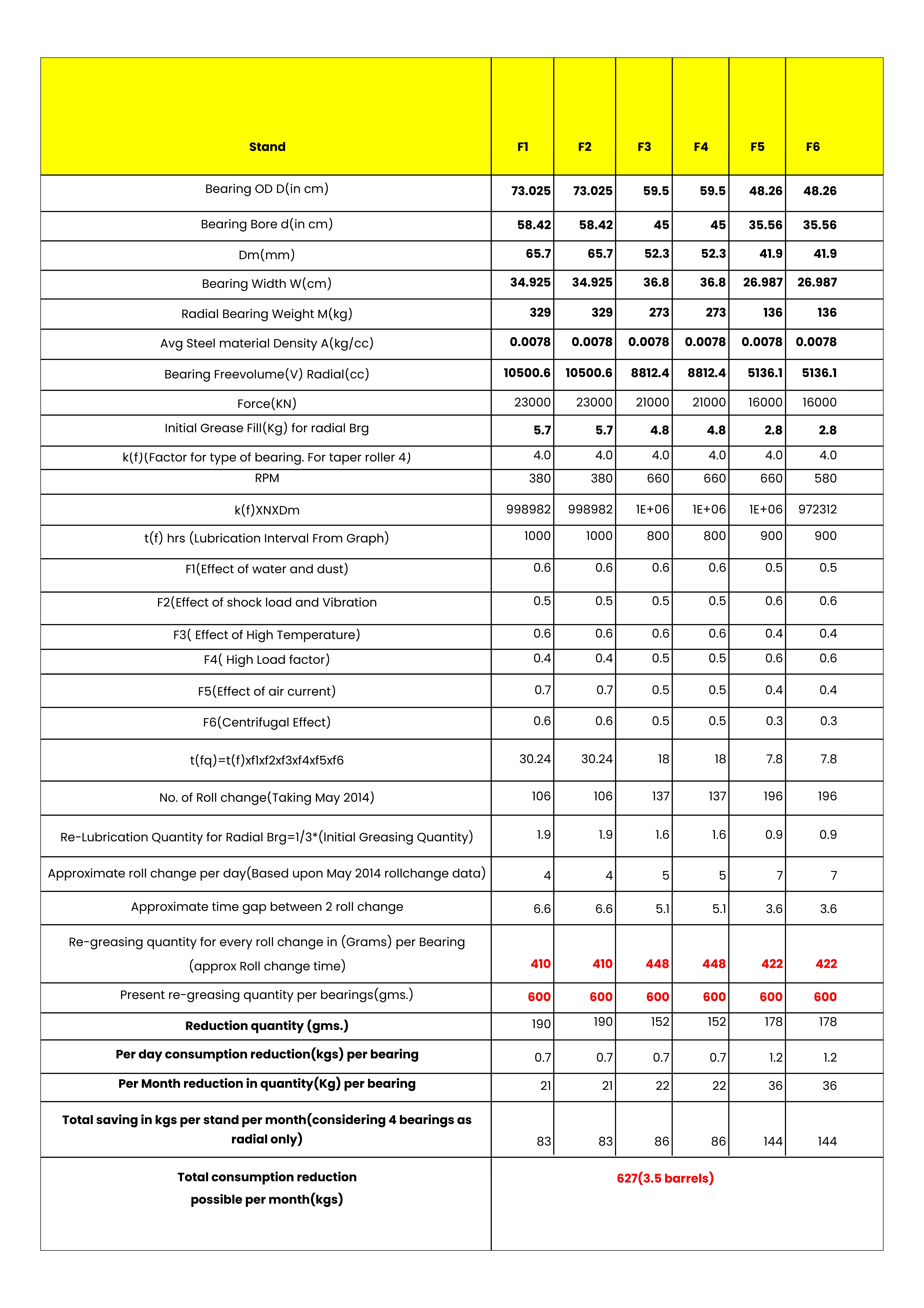
Case Study 3: Calculation of Grease Quantity & Relubrication Interval for TSCR Mill Stands
TSCR (Thin Slab Rolling and Casting) mill in TSL is an integrated mill along with steel making, casting, and rolling. TSCR caters its product to high-end segments like the automobile sector, CRM, the LPG sector, etc. TSCR is a department where quality strips are rolled with a production capacity of 2.4 MTPA.
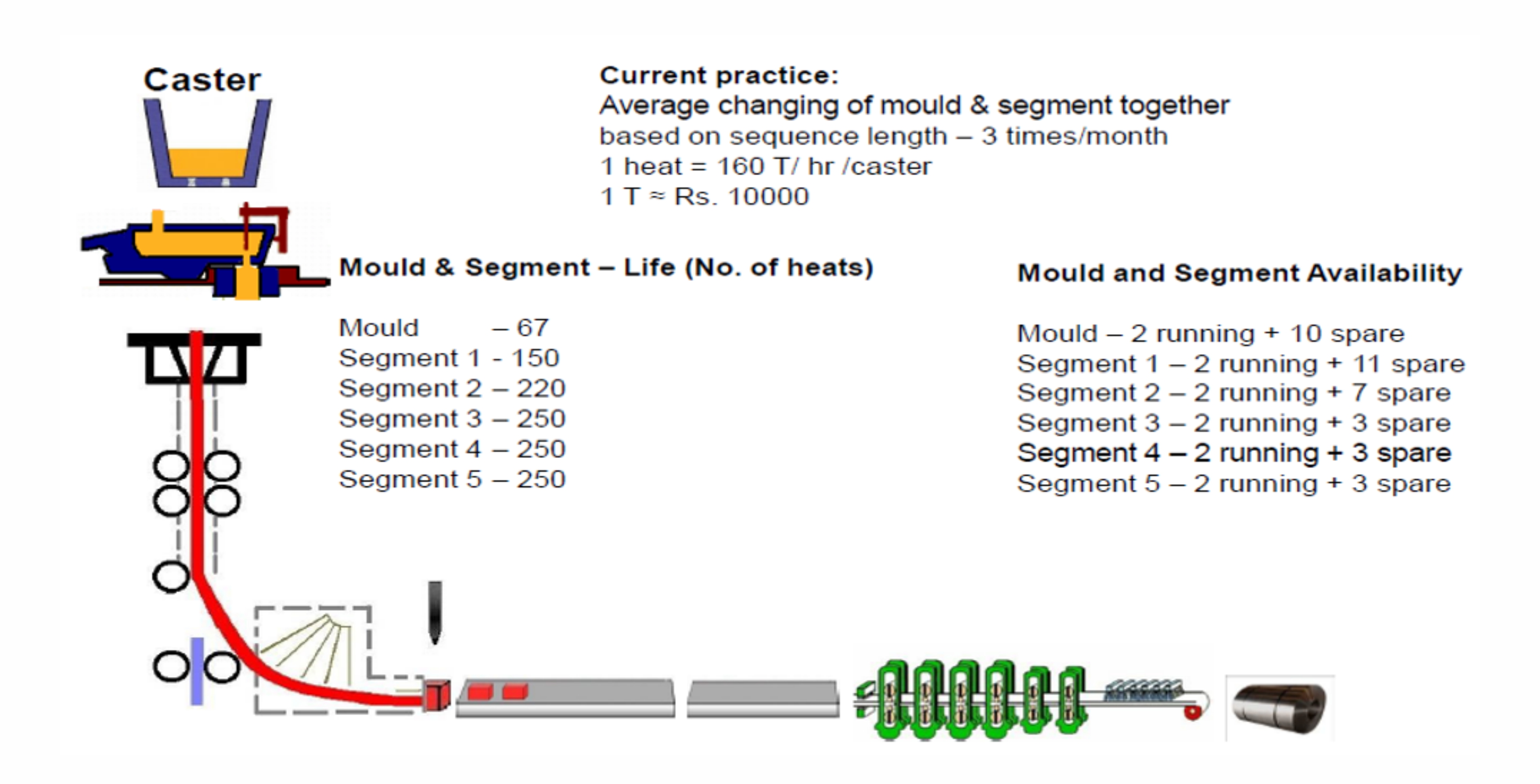
Calculation of the exact quantity of grease and relubrication interval for the Mill Stands led to a reduction in grease consumption as well as an improvement in Mill Reliability.
Conclusion
Six Rs are essential for achieving lubrication excellence. One of the examples from Nippon Steel, Japan, is shown below.
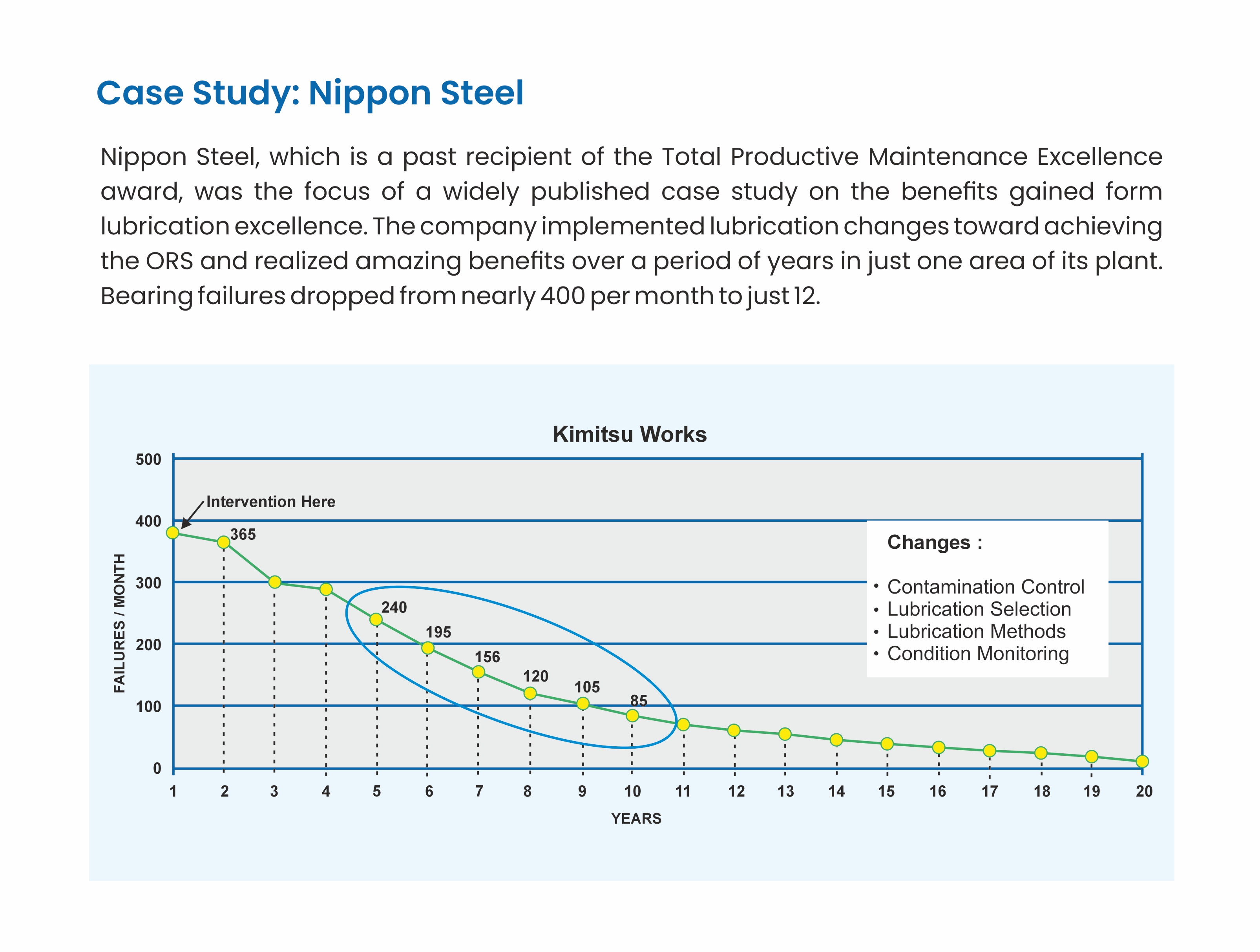
Tata Steel has also been able to achieve significant improvement in Plant Reliability through the implementation of the Six Rs of lubrication management.